Model based markerless tracking
Model based markerless tracking
OUTPUT
OVERVIEW
For our project we would like to implement a markerless augmented reality application on a mobile device. We would like to use an android device for this project. The goal of the project is to implement a real time tracking system using a model of a simple object, like a rubik’s cube. The principal deliverable in this project is a model-based tracking system implemented on a mobile device. We plan to implement the tracking algorithm ourselves. We will not use any in-built tracking tools available in ARtoolkit.
Milestones:
Camera Calibration:
The first step in the project is to calibrate the camera on the mobile device.Accurate camera calibration is essential for implementing a good tracking system. This can be done using the Camera Calibration plugin provided by the ARToolKit orMATLAB.
Object tracking and camera pose estimation:
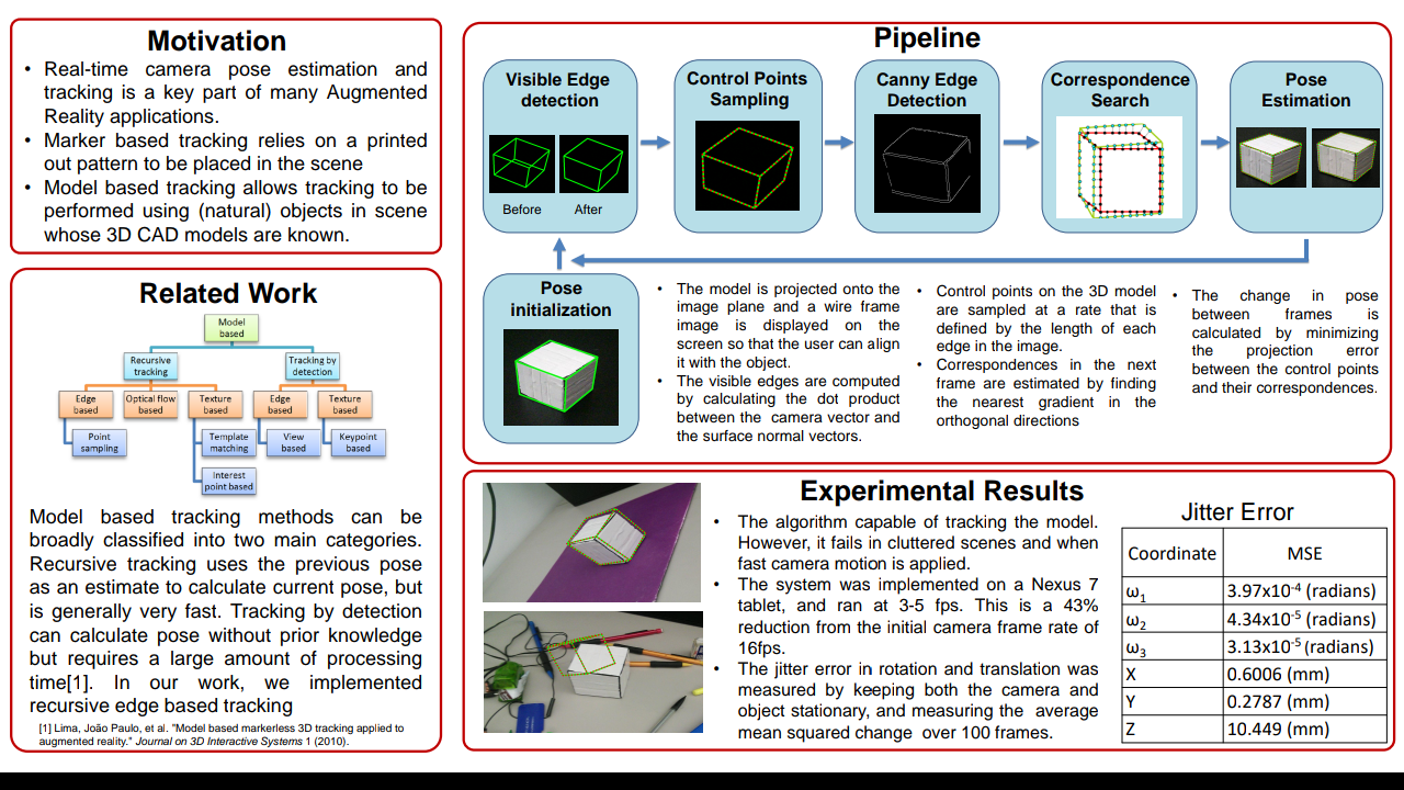
Next we would like to estimate the camera’s pose by using a control object whose CAD model is known. The control object used will be a simple cube like a rubik' cube or a cardboard box. We would like to use the point sampling edge based technique described in [3] to track the camera’s pose. This is a recursive tracking technique in which the pose calculated in the previous frame is used as an initial estimate to calculate the pose in the current frame. Point sampling algorithms are composed of four components, control points sampling, visible edge detection, control point matching, and pose estimation.Control points sampling First point sampling is performed by finding the control points. Control points are points that lie along the edges of the 3D model, which in our case would be a cube.
These points will later be compared to the edges found in the image. The points will be sampled uniformly so that each edge in the model has the same amount of points per unit length.Visible edges detection Since some of the edges of a cube will always be occluded in the image, we must determine which edges are actually visible. This way we will know which edges
will have correspondences in the image. The process proposed by [1] is as follows.Each edge in the model will be labeled with a unique ID number. Based on the previous known position of the object, the model will be projected into the camera frame. All ofthe edges that would be self-occluded are then removed. The control points are sampled from the remaining edges, and are checked by comparing the ID number of the edge to the ID numbers of the removed edges.Control points matching The visible edges in the CAD model are matched to those of the true object using the Moving Edges algorithm [4]. Each visible edge is first projected onto the image plane using the previously computed pose of the camera. For each control point on the edge, a line search is performed in the direction perpendicular to the edge in order to find pixels with strong gradients. Strong gradients are an indicator of an edge in the image. The point of strongest gradient close to the chosen control point is assumed to be the corresponding point on the true edge of the object in the scene. Pose calculation Using the camera pose in the previous frame as an initialization, the current pose of the camera is calculated by minimizing the distances between the chosen control
points and their matches using Levenberg-Marquardt algorithm.
Performance Metrics:
There are two main metrics that we will use to evaluate our algorithm. The first is the accuracy of the estimated pose. To determine the ground truth, we will cover each face of a test cube with a known checkerboard pattern. For each image frame, the pose estimated using the checkerboard pattern will serve as ground truth. We will compare this to the pose of the camera estimated using our algorithm. By comparing errors across successive frames, we can also check the robustness of the algorithm to fast movements of the camera. The other performance metric we will use is the runtime of the algorithm. Sincewe would like to implement this tracking on an android device, we would like the runtime to be as low as possible so that it can run in real time.
Stretch goals:
If time permits, and we have a stable tracking algorithm, we would like to be able
to render a basic 3d object on the phone. We would render a something simple and well
known like the Utah teapot into a scene. Using the estimated changes in rotation and
translation the user could see different parts of the teapot as the camera moved.
Timeline:
● Camera calibration 11/12 - 11/15
● Control points sampling 11/15 - 11/ 18
● Visible edges detection 11/18 - 11/23
● Control points matching 11/23 - 11/29
● Pose calculation 11/29 - 12/3
● Performance evaluation 12/3 - 12/6
References:
1. Lima, João Paulo, et al. "Model based markerless 3D tracking applied to
augmented reality." Journal on 3D Interactive Systems 1 (2010).
2. Barandiarán, Javier, and Diego Borro. "Edge-Based Markerless 3D Tracking of
Rigid Objects." Artificial Reality and Telexistence, 17th International Conference
on. IEEE, 2007.
3. Wuest, Harald, Florent Vial, and D. Strieker. "Adaptive line tracking with multiple
hypotheses for augmented reality." Fourth IEEE and ACM International
Symposium on Mixed and Augmented Reality (ISMAR'05). IEEE, 2005.
4. Bouthemy, Patrick. "A maximum likelihood framework for determining moving
edges." IEEE Transactions on Pattern Analysis and Machine Intelligence 11.5
FOR BASE PAPER PLEASE MAIL US
DOWNLOAD SOURCE CODE CLICK HERE
OUTPUT
OVERVIEW
For our project we would like to implement a markerless augmented reality application on a mobile device. We would like to use an android device for this project. The goal of the project is to implement a real time tracking system using a model of a simple object, like a rubik’s cube. The principal deliverable in this project is a model-based tracking system implemented on a mobile device. We plan to implement the tracking algorithm ourselves. We will not use any in-built tracking tools available in ARtoolkit.
Milestones:
Camera Calibration:
The first step in the project is to calibrate the camera on the mobile device.Accurate camera calibration is essential for implementing a good tracking system. This can be done using the Camera Calibration plugin provided by the ARToolKit orMATLAB.
Object tracking and camera pose estimation:
Next we would like to estimate the camera’s pose by using a control object whose CAD model is known. The control object used will be a simple cube like a rubik' cube or a cardboard box. We would like to use the point sampling edge based technique described in [3] to track the camera’s pose. This is a recursive tracking technique in which the pose calculated in the previous frame is used as an initial estimate to calculate the pose in the current frame. Point sampling algorithms are composed of four components, control points sampling, visible edge detection, control point matching, and pose estimation.Control points sampling First point sampling is performed by finding the control points. Control points are points that lie along the edges of the 3D model, which in our case would be a cube.
These points will later be compared to the edges found in the image. The points will be sampled uniformly so that each edge in the model has the same amount of points per unit length.Visible edges detection Since some of the edges of a cube will always be occluded in the image, we must determine which edges are actually visible. This way we will know which edges
will have correspondences in the image. The process proposed by [1] is as follows.Each edge in the model will be labeled with a unique ID number. Based on the previous known position of the object, the model will be projected into the camera frame. All ofthe edges that would be self-occluded are then removed. The control points are sampled from the remaining edges, and are checked by comparing the ID number of the edge to the ID numbers of the removed edges.Control points matching The visible edges in the CAD model are matched to those of the true object using the Moving Edges algorithm [4]. Each visible edge is first projected onto the image plane using the previously computed pose of the camera. For each control point on the edge, a line search is performed in the direction perpendicular to the edge in order to find pixels with strong gradients. Strong gradients are an indicator of an edge in the image. The point of strongest gradient close to the chosen control point is assumed to be the corresponding point on the true edge of the object in the scene. Pose calculation Using the camera pose in the previous frame as an initialization, the current pose of the camera is calculated by minimizing the distances between the chosen control
points and their matches using Levenberg-Marquardt algorithm.
Performance Metrics:
There are two main metrics that we will use to evaluate our algorithm. The first is the accuracy of the estimated pose. To determine the ground truth, we will cover each face of a test cube with a known checkerboard pattern. For each image frame, the pose estimated using the checkerboard pattern will serve as ground truth. We will compare this to the pose of the camera estimated using our algorithm. By comparing errors across successive frames, we can also check the robustness of the algorithm to fast movements of the camera. The other performance metric we will use is the runtime of the algorithm. Sincewe would like to implement this tracking on an android device, we would like the runtime to be as low as possible so that it can run in real time.
Stretch goals:
If time permits, and we have a stable tracking algorithm, we would like to be able
to render a basic 3d object on the phone. We would render a something simple and well
known like the Utah teapot into a scene. Using the estimated changes in rotation and
translation the user could see different parts of the teapot as the camera moved.
Timeline:
● Camera calibration 11/12 - 11/15
● Control points sampling 11/15 - 11/ 18
● Visible edges detection 11/18 - 11/23
● Control points matching 11/23 - 11/29
● Pose calculation 11/29 - 12/3
● Performance evaluation 12/3 - 12/6
References:
1. Lima, João Paulo, et al. "Model based markerless 3D tracking applied to
augmented reality." Journal on 3D Interactive Systems 1 (2010).
2. Barandiarán, Javier, and Diego Borro. "Edge-Based Markerless 3D Tracking of
Rigid Objects." Artificial Reality and Telexistence, 17th International Conference
on. IEEE, 2007.
3. Wuest, Harald, Florent Vial, and D. Strieker. "Adaptive line tracking with multiple
hypotheses for augmented reality." Fourth IEEE and ACM International
Symposium on Mixed and Augmented Reality (ISMAR'05). IEEE, 2005.
4. Bouthemy, Patrick. "A maximum likelihood framework for determining moving
edges." IEEE Transactions on Pattern Analysis and Machine Intelligence 11.5
FOR BASE PAPER PLEASE MAIL US
DOWNLOAD SOURCE CODE CLICK HERE


Comments
Post a Comment